I have a Raspberry Pi 3 and Zero 1.3, Which I believe the GPIO pin-outs for both are the same but for the moment lets say just the RPI 3, I have followed everything i have come across on the internet from forums like this site’s to youtube… I can’t get this to work, I used these instructions https://discourse.osmc.tv/t/howto-lcd-hd44780-on-raspberry-pi-2/10639 and I just can’t get it to work! I am a returning RPI user who gave it up for a while but at one time had XBMC working on a RPI B+ with the same 20x4 lcd hd44780 but for some reason the knowledge has been lost… Please help me, And try to keep it simple, i know nothing is simple when explaining things, but maybe go line by line so i can try to step this thing to completion, also please don’t refer me to a 12 year old neighbor this time and actually help. I know there are alot of people on here with exp where it comes to OSMC and the LCD, maybe im missing something simple along the way!
Thank you all for your time!
-Paul
Did you use exactly the pins from this tutorial and the .so file that is linked there?
pin out is
vss - ground
vdd - 5v
vo - 10k pot (contrast)
rs - Pin 26 (GPIO 7)
rw - Ground
e - Pin 24 (GPIO 8)
d0 NA
d1 NA
d2 NA
d3 NA
d4 - Pin 22 (GPIO 25)
d5 - Pin 18 (GPIO 24)
d6 - Pin 16 (GPIO 23)
d7 - Pin 12 (GPIO 18)
a - 10k Pot (Brightness)
k - Ground
And I downloaded this .so file off this thread (sorry i linked the wrong one)
https://discourse.osmc.tv/t/howto-lcd-hd44780/6304
maybe im outta my league here lol i cant even seem to link the right thread!
Try this so file:
http://sourceforge.net/p/lcdproc/patches/_discuss/thread/4c659fe3/b8f3/attachment/hd44780.so
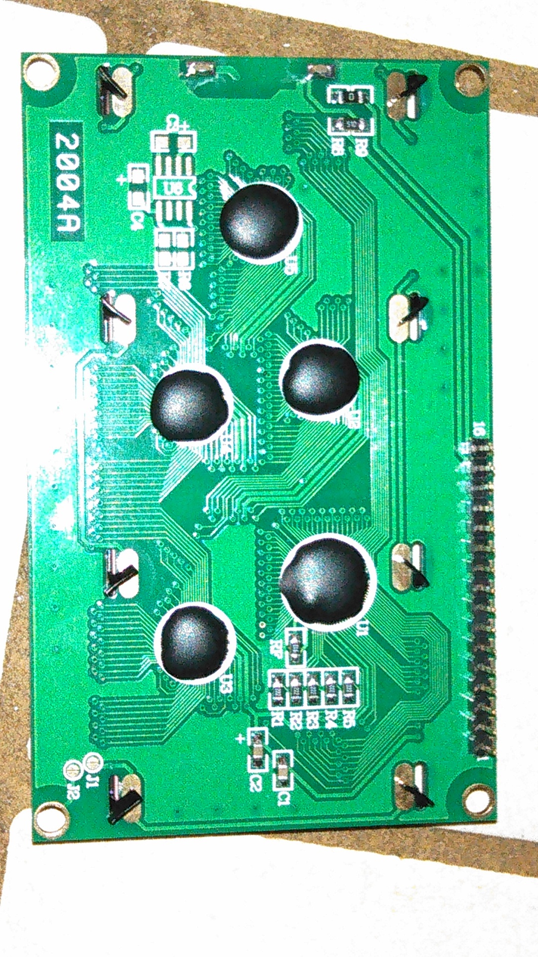
Can you give a link to the exact lcd you bought (not only lookalike) and its datasheet please?
What do you see on the lcd?
White rectangles in the upper row or nothing at all?
Can you take a photo of the connections on rpi and the lcd plase?
Okay keeping in mind i made my own board using a RPI proto board, here is what i have… I also used a DMM and made sure all the wires are connected properly on the board… I dont know unless the grounds on the PI’s GPIO pins matter cause the 2 ground connections on the board seem to be different ground pins on the PI
https://www.amazon.com/gp/product/B01G8DPGWY/ref=oh_aui_detailpage_o02_s00?ie=UTF8&psc=1
https://www.amazon.com/gp/product/B00D7Z2BWU/ref=oh_aui_detailpage_o03_s01?ie=UTF8&psc=1

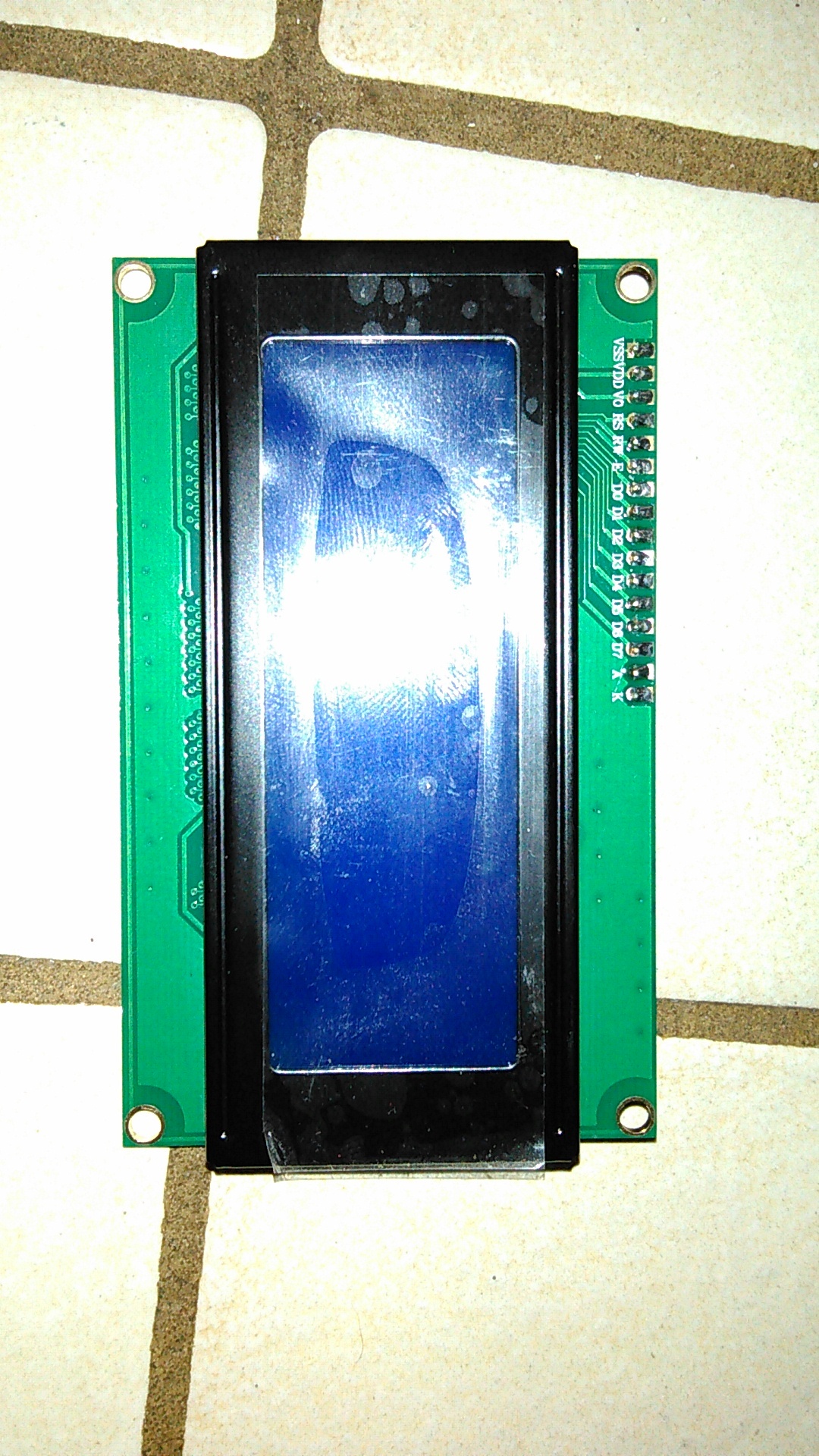
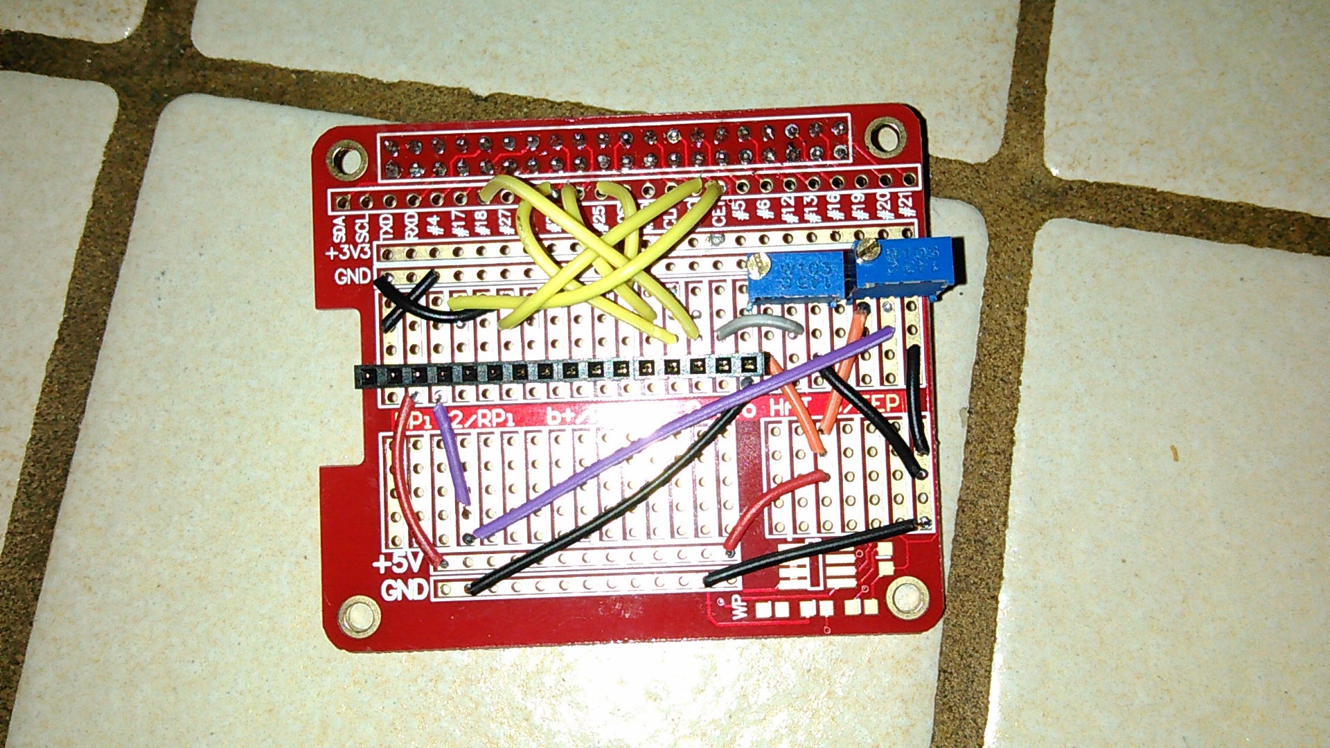
Oh sorry also I see what I remember from my old 20x4 project blue screen, backlight working i can turn it up and down with the pot and there is darker blue squares where the characters would be
Did you try the. so I linked to?
YES IT WORKS!!!

Thank you so much for your help I really appreciate it! As soon as I downloaded the file and copied it over and rebooted it started right up! I feel bad for asking after all that but i have another screen, same thing. Would it work on a zero if i were to do all the same steps? I think the Zero’s gpio setup is the same and i have a copy of OSMC running on my zero too.
The so I linked to is a patched version for the Pi2.
You have to use a different one for the pi zero.
The pi zero is a Pi1 hardwarewise, so just search for a tutorial for a pi1 on the web. It should work.
Thank you for your help! I am off to work now but when i get home ill try it out on the zero with the Pi1 info