Seeing @Toast’s excellent guide on how to make lightberry work on OSMC as well as threads on using hyperion with lightpack etc. has reignited my urge to get an ambilight clone for my TV.
Most of these packaged products (Lightberry, lightpack) seemingly “just” put together off the shelf products. Before, it seemed that their main service was providing software for their solutions but now with Hyperion running the lights and other config tools that part of the deal seems to have been one-upped. And off the bat all these packs probably charge a premium for their offerings…
Or so I thought… I’ve been reading up on some tutorials on how to make one yourself (including the wiki for the hyperion project). For me everything with a soldering iron is disqualified (which makes this hard), even when looking for parts on aliexpress I have a hard time getting it much cheaper than the pre-packaged products…
So I thought, why not “crowd source” this? And see if we together can find the cheapest way to get ambilight for our OSMC TV sets
What size of TV do you have?
Do you have a Pi (to act as controller)?
Do you want leds all round, just the sides or sides and top?
The product you link to has 40 LEDs and might not be that impressive on a larger TV. I have 64 LEDS on a 48 inch TV (16 left, 16 right, 32 across the top, so none on the bottom) and it works a treat. I think the more leds (within reason) the more localised and better the effect.
It seems some (if not all) strips are designed so that they can be plugged together in various configurations. e.g. for LPD8806 (which I used and did solder) I could have purchased some “4 Lead JST-SM connectors” this would put the price up but reduce the soldering required.
All I needed was a 2mtr length of these $30 for 1Mtr (32 leds) because I already had the Pi and a high output power supply lying around.
So for $60 (~= GBP 38) (+postage) with lots more LEDs I was up and running! Soldering was a bit tricky though.
I’m using a raspberry pi 2 and have a 40’’ TV, so yeah 40 LEDs would be on the low side for that size TV. Depending on the number of LEDS I eventually get I’ll either run them like you or on the bottom as well.
The item description in the link in the OP mentions other options but I can’t see if they’re actually available, one could always send an email to their “english support” and ask.
Interesting with the “4 Lead JST-SM connectors”, you say they reduce the soldering required - But there’s still some soldering left?
I could find the same LED strip that you used for 11 usr with free shipping - That would cut your setup down to an incredible 22 usd!
I would however need (at least) both connectors and a power supply:
LED-strip - Depending on colour, waterproof or not: 7.16-8.46 GBP (setup needs at least 2 of these) Power-supply - Depending on amp output, but going for 5v, 6A: 7.16 GBP JST-connectors - Going for 2 pairs: 3.71 GBP (5 pairs are only 4.33 GBP)
Total: Around 27 GBP (or 42 USD)
We still need something to connect the LEDs to the gpio - And I’m guessing this part still needs soldering? Or some other connecting wires?
These Leads should do the job one end plugs directly onto the GPIO pins the other end will need to be cut/stripped and connected to the led leads (you will probably get away with some small universal screw connectors like these from any electrical store - but I can’t guarantee it)
To complicate things the leds don’t wrap around corners too tightly so you may need right angle joint connectors for each corner you are going to have the leds wrap around. also is there a flat border around the back of the TV on the edges that the leds can be secured to?
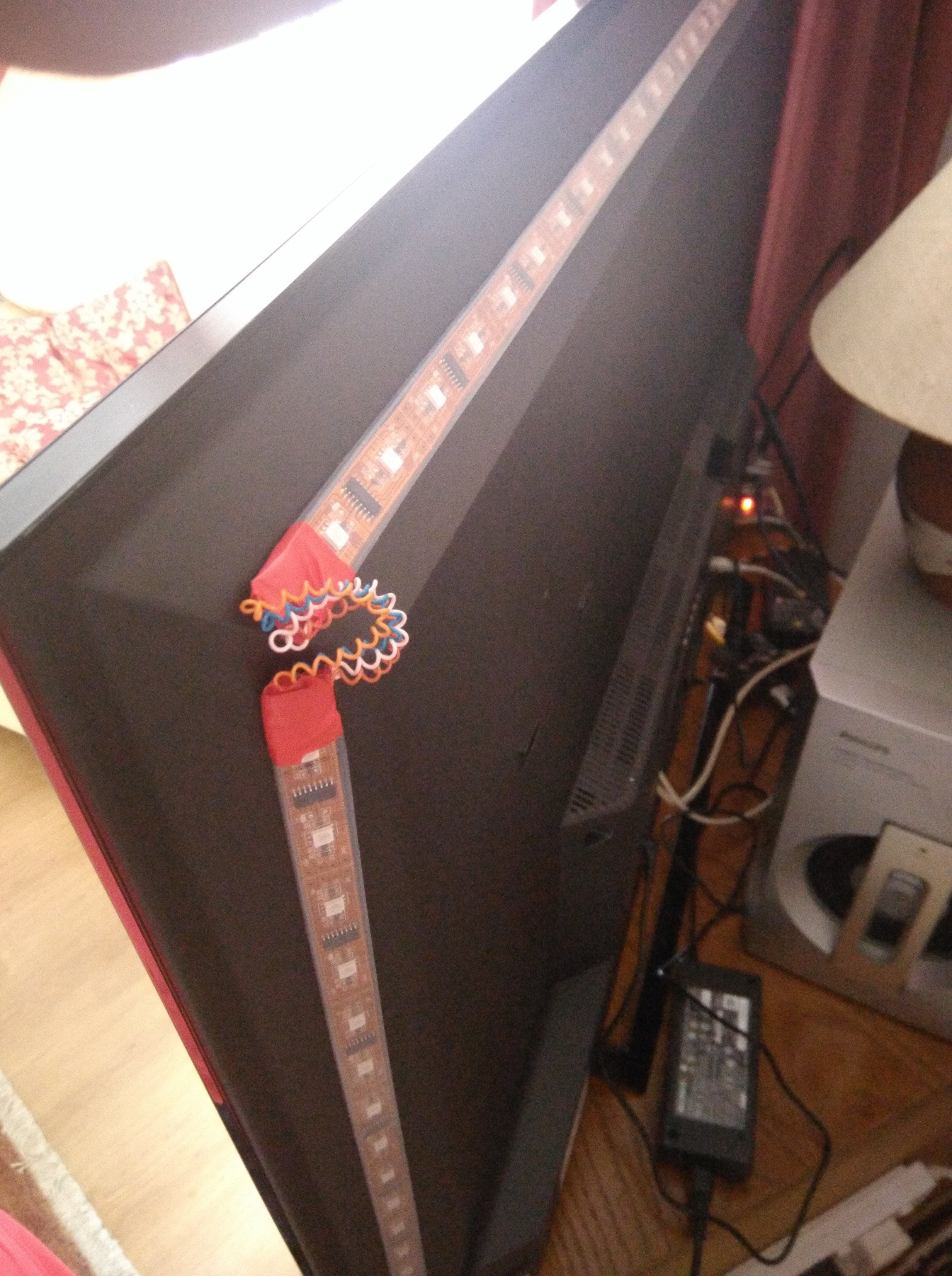
On my TV there is an angled edge where the casing gradually widens and it gives a perfect surface for mounting the leds (flat surface will direct the led light directly behind the tv but this angled surface throws the led light out and slightly away from the tv) this also complicates the connection of the led corners though (I cut the strip at each corner and soldered wire extensions between them to easily accommodate the curved joints)
Note the lamp sitting on top of the sub-woofer that has been there for ten years or more - i always wanted/needed light behind the TV to soften the edges in a dark corner but the LEDS have rendered this redundant for the last year or more, even without TV on or XBMC driving them I use Hyperion’s Andriod app to control their colour and brightness - I love them!
You will also need something to stick the leds onto the tv I used some of this double side tape
Pi mounted on back of tv with double sided tape and soldered connections between the Pi GPIO leads and the LED leads note the power-lead which drops down towards the floor and powers both the LEDs and Pi1.
Actually the wires from the Pi shop are the wrong ones (they are for breadboard connection, male/male) these are the correct ones with male/female ends (you can get female/female etc). The female end plugs onto the GPIO and the male end will be cut/stripped for connection to LEDs
Depending on where you are based the transformer you found might need a plug adapter - also the output connector won’t plug into the LEDs or the Pi, so would have to be cut and stripped for connection like the rest. I am trying to clarify in another thread if LEDs and Pi can be powered seperately - I wired mine according to a “how to” elsewhere but it is not entirely recommended because it bypasses a fuse on board the Pi .
Buying a soldering iron and learning to solder should also be an option as you can use those skills everywhere and it helps tremendously with such kind of projects
If soldering is too hard then doing it yourself isn’t really an option. Soldering a couple wires isn’t hard and it’s a skill that can be used everywhere. I honestly don’t know how someone can claim to be a do it yourselfer if they can’t solder
In essence this is correct and may be all that is required when connecting the leads from the LEDs to the GPIO header leads and power supply as the leads can be separated out inches apart from each other while being soldered . When soldering on a board or with smaller wires/components (like the corner wires on my set up above), that cannot be easily separated, some skill is required and like any skill requires patience and practice and even some risk of screwing things up. In addition though for this project it adds the cost of an iron and solder that may/may not ever be used again. On the whole though I agree it is a skill worth developing.
More info re power supplies (not to scare you or anyone else off). In another thread I was prompted to check the output voltage on my power supply to Pi and LEDs and discovered that the power supply I was using, while set to 5v was actually supplying 6v. This is not recommended for the Pi (max 5v) and at the limit of tolerance for the LEDs (even though the set up has worked for over a year) so I have decided to purchase one of these for 2 reasons…
It can supply up to 10 AMPs (more than enough for the Pi and LEDs in my case) so I could add another Pi or more LEDs or whatever additional 5v need arises.
It has a voltage adjuster so (with help of a voltage meter) I can be sure it is delivering 5v and only 5v.
(lesson from other thread: If the Pi is plugged into TV via HDMI and is over voltage, that over voltage is passed on through the HDMI potentially causing damaging to the TV) hence the need to be prudent.)
On the down side its dearer than the one selected above, its not pretty and it requires a mains lead to be manually added, which is left a little exposed, so may not be ideal if accessible to kids.
I suppose the lesson is, its no harm to email supplier and look for assurances that the power supply will do exactly what you want it to do i.e. supply 5v and only 5v to your specific number & type of LEDs + Pi.
I’m not an electrical/electronics engineer, if there are any reading this I would appreciate any corrections or input.
How did you measure those 6V?
If you had no load on it, it could actually drop the voltage down to around 5V when there actually is a power draw.
Try to measure it with the pi connected and powered on.
Might just be a badly regulated supply. The voltage under load could even be too low than too high then.
How would we go about this (other than agreeing a list of all components end to end and a DIY guide.)?
I would have bought a kit if I could have found one at the right price so I think keeping the price low is key. I also think it would be popular. Keeping price low might be possible with bulk ordering of components that are being described here.
We can’t sell it cheap as chips, but we can make it a fair price for what you get. Ideally, we’d provide the materials and an official software installation that persists across upgrades and guarantees support. As with all hardware we sell, we would provide our standard 1 year international warranty.
It’s new territory, so whether there’s demand for it is to be determined.
It could grow arms arms and legs with ‘options’ because people with different size TVs will require different LED strip lengths but perhaps offering a LED strip that is 2mtrs (and can be cut to length) might suffice.
Here’s my wish list
Power Supply (capable of power everything in one go 5v/10Amp would be a good coverall example
- preferably with two tails or a connector to split the output into two
The best way I can describe this with this four way example (not a bad example as it would provide for possible future expansion e.g. a second Pi assuming the power supply is not being overloaded - another good reason for the 10Amp one above)
Each output on the splitter would have a dedicated lead for required device to be powered in this case we need two different types (one end of each lead has the male connector that is the right fit for the splitter ouputs) the other ends are two different
one goes to micro USB plug for Pi, length to be agreed/decided
one to supply power to whatever connector is on for LEDs, length to be agreed/decided) I think there was a connector like the female one here already there that I cut off - will need to confirm.
But this second connector has the Poerw * ground on the outside pins and the data lines are the inside two (at least on the LPD8806) so the LED ends of the 2nd leads needs a seperate tail of two wires from the center pins to connect to Raspberry Pi GPIO data pins.
Maybe this is easier
LED Strip 2Mtrs there is a variety supported by Hyperion
for example: LPD8806, LPD6803, Sedu, Lightberry, Adalight,Lightpack, Paintpack (taken from the Hypercon.jar configuration utility and could be out of date). I used the LPD8806 they come in a weather proof tubing which helps keep things safe. The LPD8806 LEDs can be cut to length or can be extended by plugging (or soldering) more on.
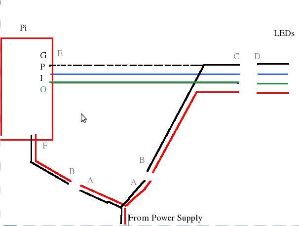
Maybe this is easier - each letter represents a different connector…
The dotted black line (between E and C) is there because I think the Grounds need to be connected.
(Mine had both Ground and Power between the LEDS and Pi directly but this config is different and I think better but needs to be confirmed by someone who knows this stuff better)
A = Female connectors from Power Supply - connecting to
B = Male connectors
F = Micro USB connector for power to Pi
E = GPIO header plugs
C = Female LED connector
D = Male LED connector
Note how the C connector has two seperate tails going in different directions - one to Pi and one to Power My guess is that the cable C,E,B needs to be specified and manufactured and I am not sure if there is an off the shelf version of B,F. But the rest are probably available off the shelf.
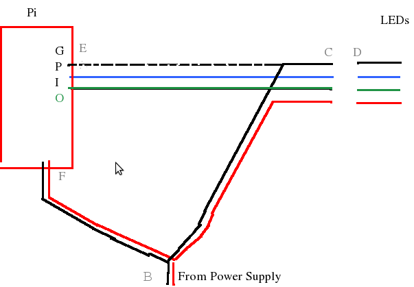
I don’t like connectors so here is an alternate where one cable incorporating E,C,B,F connectors might do the whole job.
Finally…
Raspberry Pi probably not required or optional as people may already have one
Double Sided Sticky Tape say 2.5Mtr length to mount Pi and LED strip on back of TV
The more I think about it… a suitable beefed up power supply (5v/10Amp) + one of those E,C,B,F cables might well be the killer product letting people source specified/compatible LEDs and sticky tape themselves.
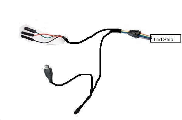
Had fun with this - the finished product (power supply omitted)…
I would have killed for this a year ago
I just want to thank you all for providing this information here. I bought all the parts and got it working in approx. 2h now I am using 112 LEDs on a 40’’ TV.
I really like how simple the installation of Hyperion is.
Here is a photo of how I soldert the edges. Even if you don’t have much experience it is definitely douable.
One last question; I am using a 3.0A 5V dc adapter and I read that each led need approx. 32mA that would make 3.5A for all LEDs. Is it ok to use these LED a little underpowered?
Is every led (r/g/b) using 32 mA or is the whole package (one spot) using 32mA max?
The worst case would be all white with full brightness, what can occur in movies or advertisements.
A short time is fine. But you can dim everything by default a bit.