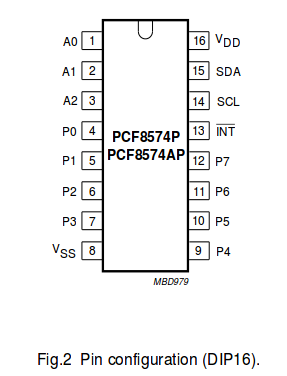
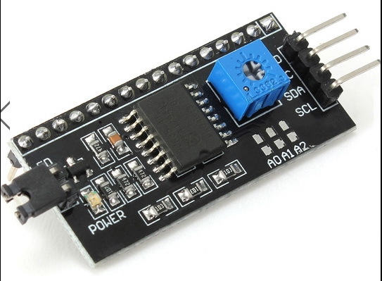
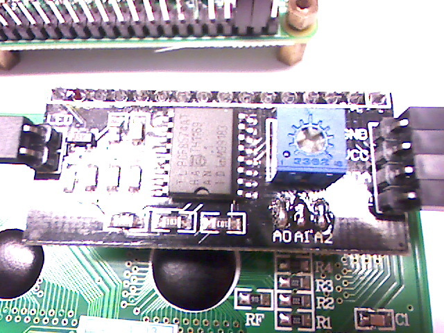
[Howto] LCD HD44780 Throught I2C Port Extender HD44780 LCD Display on Pi Throught I2C Port Extender PCF8574 Serialinterface module (LCM1602 IIC)
This guide firmly works.
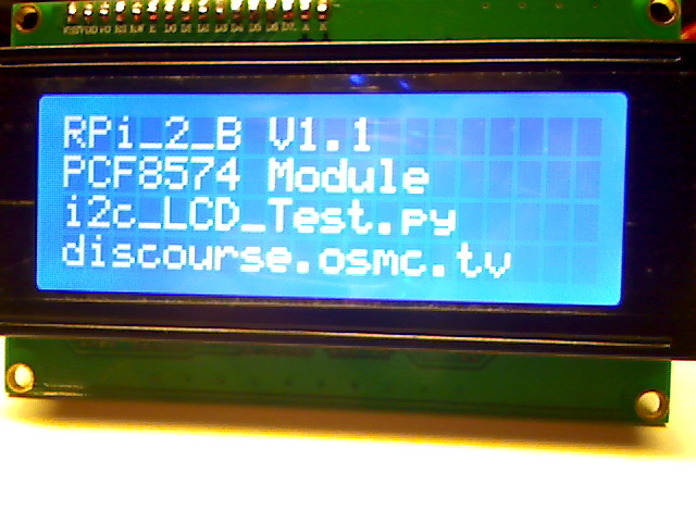
Tested on Pi-1 rev2 and Pi-2 model B, using OMSC KODI built.
Connect to your Pi via ssh and use the following commands:
sudo apt-get update && sudo apt-get dist-upgrade
sudo apt-get install i2c-tools
sudo apt-get install python-smbus
sudo apt-get install lcdproc
(select “Yes” when asked to perform an automatic configuration upgrade)
5, Enable modules
sudo modprobe i2c-bcm2708
sudo modprobe i2c-dev
Enable i2c on the pi :
sudo nano /etc/modules
Add the following lines to the file, press ctrl + x and save it:
i2c-bcm2708
i2c-dev
6, If you are running a recent Raspberry Pi (3.18 kernel or higher) you will also need to update the /boot/config.txt file.
Edit it with:
sudo nano /boot/config.txt
and add the following lines:
dtparam=i2c1=on
dtparam=i2c_arm=on
Then reboot your system:
sudo reboot
7, Check if the i2c device drivers are loaded at boot time.
lsmod|grep i2c
If the module is loaded properly, two devices should exist.
i2c_dev 7054 0
i2c_bcm2708 6128 0
8, Check which version and revision of the Raspberry Pi you have.
ls -l /dev/i2c*
The ouptut should be something like this:
crw-rw---- 1 root i2c 89, 1 Apr 2 23:38 /dev/i2c-1
" #/dev/i2c-0
"/dev/i2c-1
9, Testing the I2C address
If you’ve got an original Model B Rev 1 Pi then type the following
command :
sudo i2cdetect -y 0
If you’ve got a Model A, B Rev 2 or B+ Pi2 then type the following
command :
sudo i2cdetect -y 1
0  1  2  3  4  5  6  7  8  9  a  b  c  d  e  f
00:          -- -- -- -- -- -- -- -- -- -- -- -- --
10: -- -- -- -- -- -- -- -- -- -- -- -- -- -- -- --
20: -- -- -- -- -- -- -- -- -- -- -- -- -- -- -- --
30: -- -- -- -- -- -- -- -- 38 -- -- -- -- -- -- --
40: -- -- -- -- -- -- -- -- -- -- -- -- -- -- -- --
50: -- -- -- -- -- -- -- -- -- -- -- -- -- -- -- --
60: -- -- -- -- -- -- -- -- -- -- -- -- -- -- -- --
70: -- -- -- -- -- -- -- --
My i2c address is 0x38
10, Edit the LCDd configuration:
sudo nano /etc/LCDd.conf
Change the section:
[server]
DriverPath=/home/osmc/lcdproc/ # Note
#DriverPath=/usr/lib/arm-linux-gnueabihf/lcdproc/ # Note
Driver=hd44780
#Bind=127.0.0.1 # doesn't need for i2c module'
#Port=13666 # doesn't need for i2c module'
User=nobody
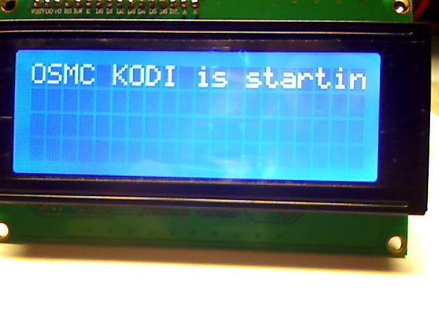
Hello="OSMC KODI is starting"
WaitTime=1
ServerScreen=no
[hd44780]
ConnectionType=i2c
Device=/dev/i2c-1 # make this i2c-0 for Revision 1 Pi's'
OutputPort=no
Port=0x38 # replace to your i2c address
Backlight=no # I didn't use Balcklight'
Size=20x4 # 16x2 or ?
DelayBus=false
DelayMult=5
Keypad=no
# edit the pin configurations for your i2c module (Note2)
i2c_line_RS=0x01
i2c_line_RW=0x02
i2c_line_EN=0x04
i2c_line_BL=0x08
i2c_line_D4=0x10
i2c_line_D5=0x20
i2c_line_D6=0x40
i2c_line_D7=0x80
After those changes reboot the pi:
sudo reboot
11, Enable/install LCDproc via OSMC In the OSMC main menu got to:
Settings >> Add-ons >> Get add-ons >> XBMC/Kodi add-on repository >>
Services >> XBMC LCDproc >> Install
“You don’t need to activate the Bind=127.0.0.1 and Port=13666 in XBMC
LCDproc menu for the i2c module”
(I think it’s only needed if you directly wired to the GPIOs without the i2c module)
Restart LCDd:
sudo /etc/init.d/LCDd restart
done.
Thanks to Rhys Williams for the right hd44780.so to allow the pin configurations to be specified via LCDd.conf.
Download Rhys’s hd44780.so from’ (Otherwise you will need to build your own .so file)
LINK
NOTE: I did make new folder for the driver. That’s much easier to copy/paste files to via FTP.
Make a folder >> /home/osmc/lcdproc/ << and drop the hd44780.so file.
MOTE2: The pin configurations for My PCF8574 Serial interface module are called “LCM1602 IIC”
.
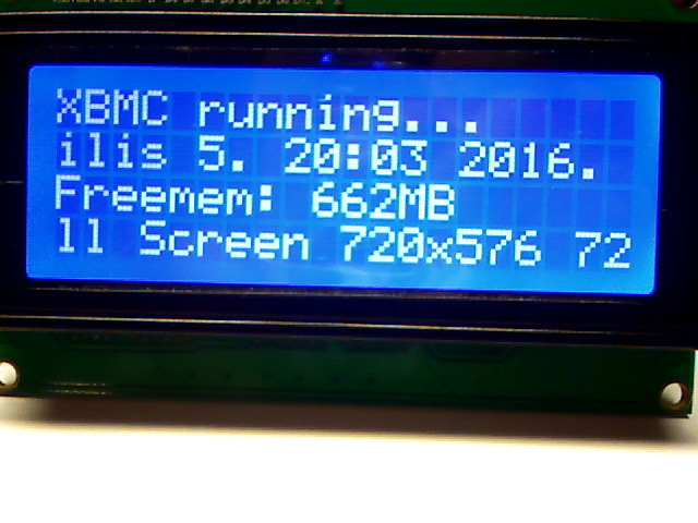
The result:
Side Note:Thanks to our @mcobit is a stud muffin for refined My text in perfect English ![]()